











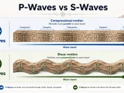


Engineering Geology
Engineering geology is the application of geological science to the planning, design, construction and operation of engineering works. It characterizes soil, rock, groundwater, geological structures and geological hazards to establish how ground conditions may affect buildings, tunnels, roads, dams and other infrastructure.
Engineering geologists develop ground models using mapping, subsurface investigations, testing and geological interpretation. These models support geotechnical design and the management of uncertainty throughout a project’s life.
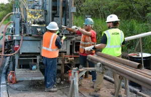
Site Investigation and Geological Mapping
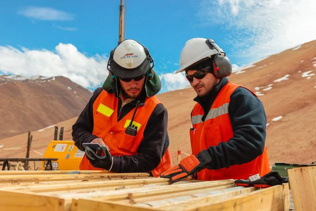
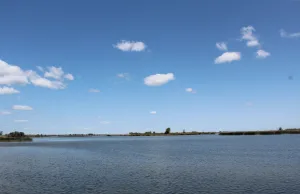
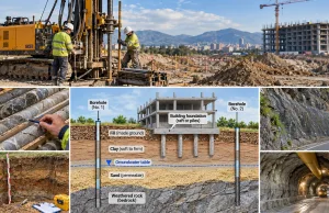
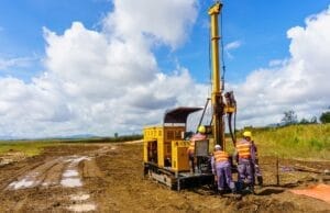
A ground investigation starts with a review of proposed works, geological maps, previous investigations, historical land use and groundwater records. A site walkover identifies exposures, drainage, unstable slopes and old excavations. Exploratory locations and depths depend on geological variability, construction loads and project requirements rather than a universal spacing or depth.
| Method | Principal information |
|---|---|
| Trial pits | Shallow soil profile, fill, contacts and accessible samples |
| Boreholes | Vertical succession, sampling, groundwater and access for testing |
| Core drilling | Rock lithology, recovery, discontinuities and weathering |
| Geophysical survey | Indirect subsurface contrasts and possible lateral continuity |
| Monitoring | Groundwater levels and ground movement over time |
A ground investigation should evolve as new evidence becomes available. Geophysical interpretations are non-unique and normally require calibration against direct observations. Read Site Investigation Techniques.
The Engineering Geological Ground Model
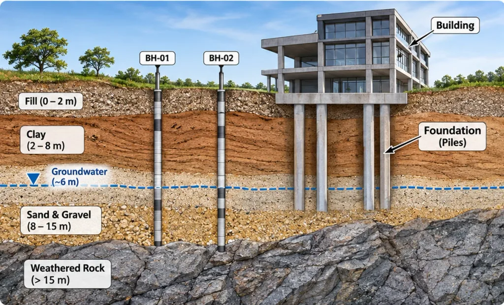
A ground model interprets the distribution of materials, geological boundaries, structures, groundwater and relevant processes. A borehole represents local observations, not proof of continuous conditions across a site. Engineering geological units group materials with relevant similarities for the project.
- Record depths, material descriptions, samples, tests and groundwater observations.
- Construct geological sections showing interpreted boundaries and uncertainty.
- Separate observations from inferred geometry and design assumptions.
- Update the model during construction when new ground is exposed.
Soil Mechanics and Engineering Properties
Soils consist of solid particles, water and air. Their engineering behavior depends on mineralogy, grain size, packing, fabric, stress history, saturation and drainage. Sand is not automatically suitable for foundations, and clay is not automatically unsuitable.
| Property | Engineering relevance |
|---|---|
| Grain-size distribution and plasticity | Classification and behavior |
| Density and water content | State of soil and compaction |
| Shear strength | Resistance to failure |
| Compressibility and consolidation | Magnitude and rate of settlement |
| Hydraulic conductivity | Water flow under hydraulic gradients |
Effective Stress and Shear Strength
For saturated soil under the usual effective-stress formulation, σ′ = σ − u, where σ is total normal stress and u is pore-water pressure. If total normal stress is 150 kPa and pore pressure is 60 kPa, effective normal stress is 90 kPa. Water pressure changes can therefore affect strength and deformation.
The Mohr–Coulomb model expresses drained shear strength as τf = c′ + σ′ tan φ′, where c′ is effective cohesion and φ′ is effective friction angle. It is an idealization applicable within an appropriate stress range. Undrained behavior needs suitable testing and analysis rather than direct substitution of drained parameters.
Rock Mechanics and Rock Mass Characterization
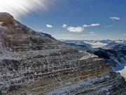
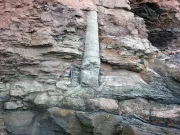
Intact rock strength differs from rock mass strength. Joints, bedding, faults, weak infill, weathering and water pressure may govern the stability of a rock mass even when intact rock is strong.
| Observation or parameter | Purpose |
|---|---|
| Core recovery | Recovered core length relative to drilling run |
| RQD | Percentage of a core run represented by sound intact pieces at least 100 mm long, under the applicable measurement procedure |
| Discontinuities | Orientation, spacing, persistence, aperture, roughness and infill |
| UCS and point load | Intact rock strength or strength index |
| RMR, Q and GSI | Rock mass classification or characterization frameworks |
Rock mass classifications are not interchangeable and do not replace project-specific stability analysis. Discontinuity geometry and water pressure often control engineering performance.
In-Situ Geotechnical Testing
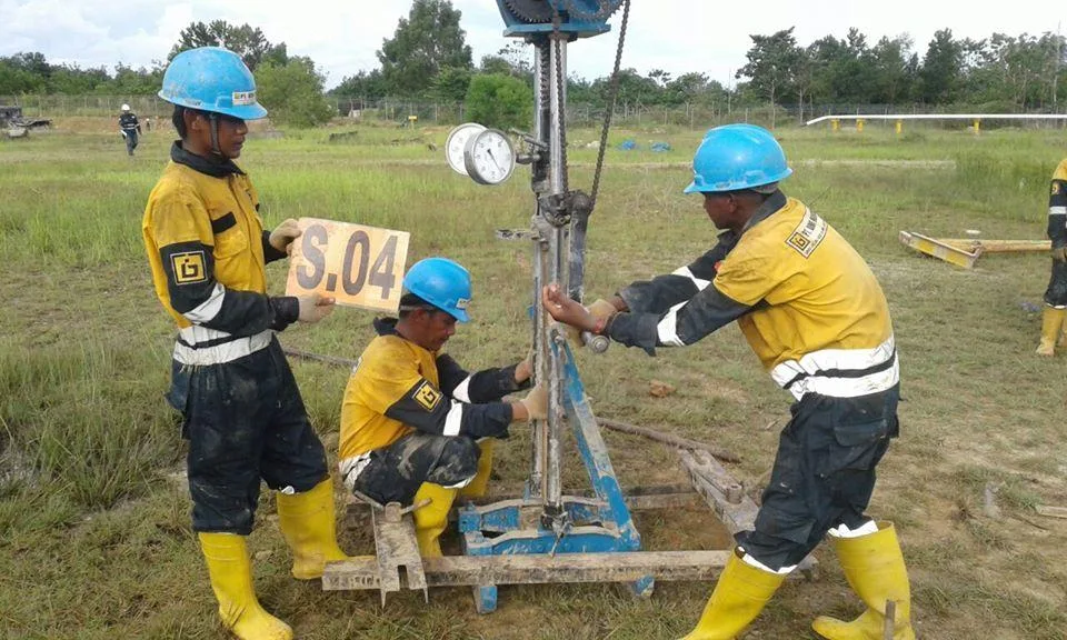
| Test | Measured result | Interpretation |
|---|---|---|
| SPT | Blows for final 300 mm of penetration after seating | Soil resistance and appropriately corrected correlations |
| CPT / CPTu | Cone resistance, sleeve friction and pore pressure for CPTu | Soil behavior and stratigraphy |
| Dynamic penetration | Blow count or dynamic resistance for specified equipment | Relative ground resistance and variability |
| Ménard pressuremeter | Pressure–volume response in borehole | Pressuremeter modulus EM and limit pressure PL |
| Field vane shear | Torque during vane rotation | Undrained shear strength of suitable soft cohesive soils |
| Hydraulic tests | Water flow or head response | Hydraulic characteristics at tested scale |
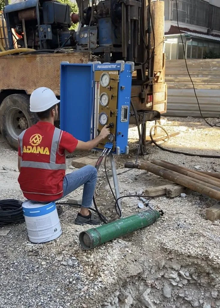
SPT values may require corrections for delivered energy, equipment and other factors. CPT and dynamic penetration correlations depend on soil type and calibration. The pressuremeter modulus is an operational parameter, not automatically equal to Young’s modulus. A single penetration resistance cannot establish a permissible foundation load without further interpretation. See In-Situ Testing.
Laboratory Testing of Soil and Rock

| Test | Main information |
|---|---|
| Sieve and sedimentation analysis | Particle-size distribution |
| Atterberg limits | Liquid limit, plastic limit and plasticity index |
| Proctor compaction | Dry density–water content relationship |
| Oedometer | One-dimensional compression and consolidation |
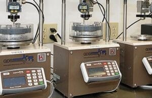
| Direct shear and triaxial | Strength under specified stress and drainage conditions |
| UCS and point-load testing | Intact rock strength or strength index |
Sample quality, disturbance, storage, orientation and stress history influence test results. Laboratory results must be interpreted alongside field observations and geological context. See Laboratory Tests of Soil and Rock Samples.
Groundwater, Seepage and Excavation
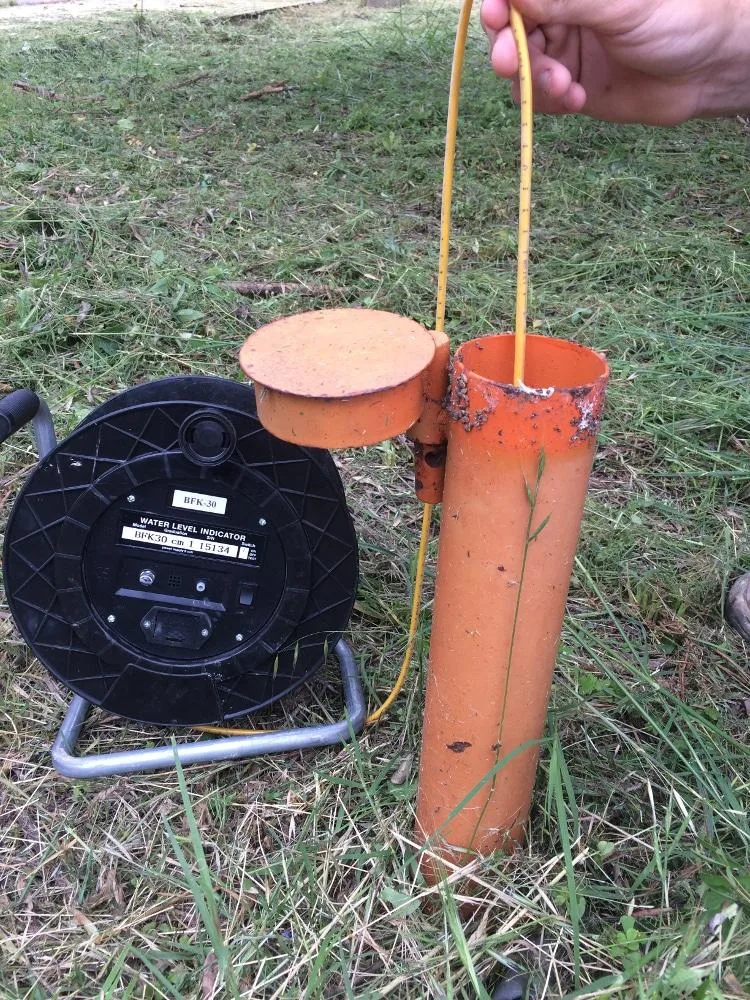
Groundwater affects effective stress, seepage forces, uplift, excavation stability and settlement. Water observed during drilling may not represent an equilibrated groundwater level. Piezometers and repeated measurements help identify perched water, confined pressures and seasonal fluctuations.
Dewatering can cause settlement beyond an excavation, alter groundwater flow and affect nearby structures or wells. Design must consider seepage, uplift, piping and basal stability. A field infiltration test for drainage design and a borehole permeability test are not interchangeable.
Geological and Geotechnical Hazards
| Hazard | Investigation focus |
|---|---|
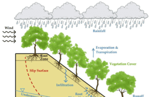
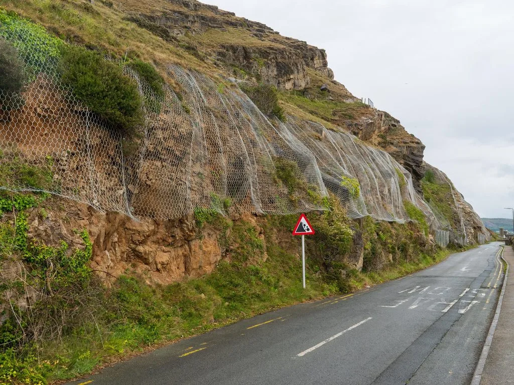
| Landslides and rockfalls | Slope geometry, discontinuities, water and movement |
| Differential settlement | Fill, compressible strata and foundation variability |
| Shrink–swell soils | Clay mineralogy, plasticity and moisture changes |
| Karst and sinkholes | Soluble rocks, drainage and cavities |
| Liquefaction | Susceptible saturated granular soils and cyclic loading |
| Seismic shaking | Regional hazard and local site response |
Risk reduction may involve avoidance, drainage, stabilization, ground improvement or suitable foundations. Read Slope Stability and Landslides and Natural Hazards.
Building Foundations and Ground Conditions
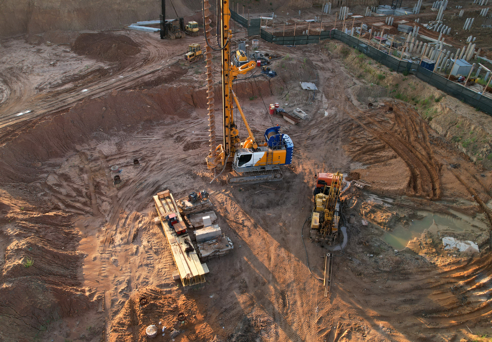
Foundation selection depends on bearing resistance, total and differential settlement, groundwater, neighboring buildings and construction constraints. Shallow foundations include isolated and strip footings and rafts. Piles and micropiles transfer loads through shaft and/or base resistance depending on the ground and system.
| Option | Reason for consideration |
|---|---|
| Isolated or strip footings | Suitable near-surface ground and acceptable settlement |
| Raft | Load distribution over a larger area and settlement considerations |
| Piles or micropiles | Deeper load transfer, settlement control or restricted access |
| Ground improvement | Modification of weak or variable strata |
Knowing only that a building has four storeys is not sufficient to select a foundation. Loads, geometry, stratigraphy, groundwater and tests are required, together with ultimate and serviceability limit-state verification. Read Engineering Geology for Construction.
Tunnels and Underground Construction

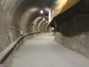
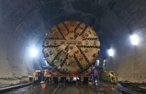
Tunnel investigations characterize rock mass quality, fault zones, abrasivity, mixed-face conditions, groundwater and possible deformation. Excavation methods include drill-and-blast, conventional mechanical excavation and tunnel boring machines (TBMs). Open, shielded, earth pressure balance and slurry machines differ in their applications.
A geological model supports equipment and preliminary support selection, but actual excavation observations and instrumentation remain essential. Potential issues include face instability, squeezing, swelling, water inflow and surface settlement. See Tunnel Construction.
Dams, Roads and Other Infrastructure

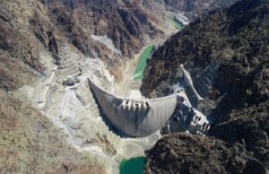
Dam projects require assessment of foundation conditions, discontinuities, seepage, abutment stability and construction materials. Roads and railways require investigation of cut slopes, embankments, drainage and soft ground. Geological conditions along linear infrastructure can vary considerably. See Dam Construction.
Engineering Geological Reports and Geotechnical Standards
Investigation reports should separate factual records from interpretation and communicate uncertainty. Deliverables commonly include plans, borehole logs, test results, groundwater observations, geological sections, ground parameters and recommendations for further investigation or monitoring.
Engineering geology emphasizes geological interpretation and ground models, while geotechnical engineering also addresses design and verification of ground–structure interaction. Responsibilities overlap and depend on professional scope and jurisdiction.
Eurocode 7 (EN 1997) provides a European framework for geotechnical design and investigation. Applicable editions, national annexes and transitional arrangements must be checked for each project. In France, NF P 94-500 organizes geotechnical engineering missions across the project life cycle.
| French mission | General purpose |
|---|---|
| G1 | Preliminary geotechnical study and initial ground risk identification |
| G2 | Geotechnical design study |
| G3 | Geotechnical execution study and follow-up |
| G4 | Supervision of geotechnical execution study and follow-up |
| G5 | Specific geotechnical diagnosis |
These introductory summaries are not substitutes for the definitive standards or project-specific professional advice.
Frequently Asked Questions
What is engineering geology?
The application of geology to ground investigation, engineering design inputs, construction and geological risk management.
How does engineering geology differ from geotechnical engineering?
Engineering geology focuses on materials, geological processes and ground models, while geotechnical engineering also analyzes and designs ground-related works.
What are common in-situ tests?
SPT, CPT/CPTu, dynamic penetration, pressuremeter, vane shear and hydraulic tests, depending on ground conditions.
Why is groundwater important for foundations?
It influences effective stress, deformation, seepage and construction conditions.
What is the difference between rock and rock mass?
Intact rock is the material itself; the rock mass includes discontinuities such as joints and faults.
Can a foundation be designed using only one penetration test?
No. Geological context, loads, settlement and appropriate design verification are also required.